The Operational Amplifier (op-Amp) and its basic amplifying configurations
Chapitre 1. Introduction to the Operational Amplifier
1.1. Vocabulary
1.2. Use
1.3. Power supply
1.4. Diagram
1.5. Ideal model
1.6. Positive and negative feedback
Chapitre 2. Basic amplifier configurations
Page d'accueilTable des matièresNiveau supérieurPage précédenteBas de la pagePage suivante

1.4. Diagram

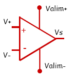
An Op-Amp has at least 5 pins :
V+ is the non-inverting input
V- is the inverting input.

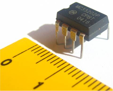
Picture of the op-amp.

This integrated circuit has 2 op-amps.
2 pins are used for the power-supply voltage.
Each op-amp uses 3 pins for V+, V- and Vs.

Usually, in order to simplify the diagrams, the power supply is not represented.

Indeed, the following two diagrams are used to represent the op-amp.

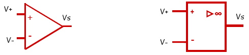
In the followings, either diagram will be used interchangeably.

Page d'accueilTable des matièresNiveau supérieurPage précédenteHaut de la pagePage suivante