PWM
In order to obtain a PWM signal with a digital circuit a continuous counter is needed. A complete counting series of the counter corresponds to one period of the PWM signal.
The frequency can hence be tuned by choosing the clock of the counter and by setting its maximum value (indicated with N in the figure). A register associated to a comparator allows to fix the duty cycle. At every counting series, the PWM output is set to 1; on the other hand, when the counter reaches the value fixed by the duty cycle register (W) the PWM output is set to 0.
Example of time diagram:
The architecture within the micro-controller is a bit more complex. Only the first 8 most significant bits of the counter maximum value are configurable.
A library of functions is provided in order to easily configure the two PWM outputs of the micro-controller.
In order to use the PWM ouput library, it is first necessary to place the following files into the project folder:
iut_pwm.h
iut_pwm.c
then to add them to the project.
After having included the library header files, it is necessary to initialize its utilization by a call to the function pwm_init at the beginning of the program.
The first parameter to pass to this function allows to choose the frequency to generate.
The value is 8-bit coded (hence between 0 and 255, indicated by N in the followings) and the frequency is calculated thanks to the following formula:
Frequency = 3.106 / (N + 1)
The second paramter allows to choose th number of outputs (1 or 2). If we choose 1, only PWM1 (pin C2) is active, activée, if we choose 2, PWM1 and PWM2 (pin C1) are active.
Note that the two outputs must work at the same frequency.
For example, in order to activate the two PWM outputs with a frequency of 20 KHz, we will use the following code:
#include <18f4550.h>
#include "iut_pwm.h"
void main(void)
{
pwm_init(149, 2);
...
}
In order to modify the duty cycle, two functions are available, one for each PWm output.
The function pwm_setdc1 controls the duty cycle of PWM1 and pwm_setdc2 the one of PWM2.
These functions receive the number of cycle at the HIGH state as a parameter.
It is 10-bit coded (hence between 0 and 1023, indicated W in the followings). The duty cycle obtained is related to the configuration of the frequency through the following formula:
Duty cycle = W / (4 (N + 1))
If W is greater than 4 (N + 1) then the duty cycle will be 1.
By using the previous configuration, (N=149), the value of W must be between 0 and 600.
We give hereafter a few values of the duty cycle as a function of W:
if N=149
| W | Duty Cycle |
| 0 |
0 |
| 150 | 0.25 |
| 300 | 0.5 |
| 450 | 0.75 |
| 600 | 1 |
Here is an example that makes the conversion of the potentiometer channel (AN0) and uses the obtained value to modify the duty cycle of PWM1. The duty cycle of PWM2 evolves in the opposite way.
#include <p18f4550.h>#include "iut_ADC.h"
#include "iut_adc.h"
#include "iut_pwm.h"
void main(void)
{
int potar = 0;
float a1, a2;
// initialisation
ADC_init();
adc_init(0);
pwm_init(149, 2);
ADC_position(0, 0);
ADC_printf("PWM1 POT PWM2");
// infinite loop
while (1) {
}potar = adc_read(0);
pwm_setdc1(potar);
pwm_setdc2(1023 - potar);
a1 = potar / 600.0;
if (a1 > 1) a1 = 1;
a2 = (1023 - potar) / 600.0;
if (a2 > 1) a2 = 1;
ADC_position(1, 0);
ADC_printf("%5.3f", a1);
ADC_position(1, 6);
ADC_printf("%4d", potar);
ADC_position(1, 11);
ADC_printf("%5.3f", a2);
}
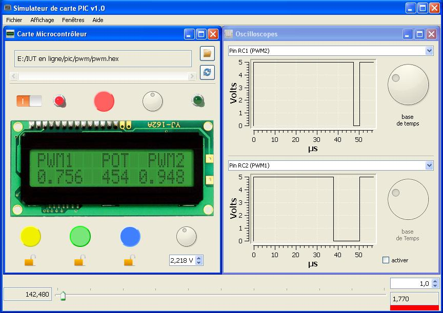
In order to display the PWM signals on a virtual oscilloscope, you select the menu “Window”, then “Oscilloscopes”.
 Download the example Zip file