Input/output ports
Pins (input/output wires) are grouped in ports.
Ports are indicated by letters. Ports A, B, C, D and E are available to the programmer.
Every pin of a port is numbered.
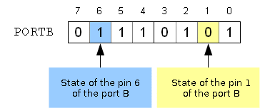
For every port, a 8-bit register (1 byte) allows to read /write the value of/to every pin (0 or 1, i.e. 0V or 5V).
These registers are indicated by PORTx where x replaces the name of the port. So, the programmer has the following registers available PORTA, PORTB, PORTC, PORTD and PORTE.
For example, for the port B, we dispose of 8 pins numbered from 7 to 0. The byte that allows to operate on this port is called PORTB.

Every pin can be configured either as a digital input or output.
When we speak of input or output, we put ourselves from the perspective of the micro-controller.
Consequently, a digital output indicates that the micro-controller imposes on the corresponding pin a 0V potential for a logical 0 and a 5V for a logical 1.
Hence, the pin behaves as a voltage source. This source can only provide a limited current, in the order of 25 mA.
An input indicates that the micro-controller sees the voltage of the pin. In this way, the micro-controller behaves as a voltmeter. An input shows a high impedance, which means that current passing through the pin is very weak (less than 200 nA)
The micro-controller will consider the pin at a logical 0 if the pin potential is 0V (or at least less than 1V) and at a logical 1 if the potential is close to 5 V (or at least greater than 4V).
Libraries configuration is obtained by mean of the TRISx register, where x replaces the name of the port.
A 1 configures the pin as an input.
A 0 configures the pin as an output.
So, TRISA controls the configuration of the pins of the port A, TRISB controls the port B, etc.This configuration is generally put at the beginning of the program.
By default, when the micro-controller is powered-up, all pins are configured as inputs.
Examples :
On our card three buttons and a LED are connected.
The buttons BP0, BP1 and BP2 are connected respectively to pins 3, 4 and 5 of port B.
The LED is connected to pin 6 of port A.
So, we need to configure the pins 3,4 and 5 of the port B as inputs and the pin 6 of port A as output.
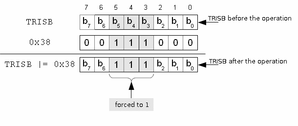
Buttons are connected as inputs of the micro-controller. Hence, we must force to 1 the bits 3,4 and 5 of TRISB register.
TRISB |= 0x38;

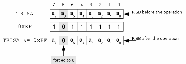
A LED is connected to an output of the micro-controller. So, we must force to 0 the bit 6 of the TRISA register.
TRISA &= 0xBF;
