The Operational Amplifier (op-Amp) and its basic amplifying configurations
Chapter 1. Introduction to the Operational Amplifier
Chapter 2. Basic amplifier configurations
2.1. Inverting configuration
2.2. Non inverting configuration
2.2.1. Characteristics
2.2.2. Virtual Lab
2.2.3. Interactive exercise
2.3. Review of the two basics op-amp configurations
2.4. Op-amp voltage follower configuration
2.5. Adder
2.6. Subtractor
2.7. Interactive exercise : name the basic functions
2.8. Virtual Lab : review of the 5 Op-Amp configurations tath we have studied
Page d'accueilTable des matièresNiveau supérieurPage précédenteBas de la pagePage suivante

2.2.1. Characteristics

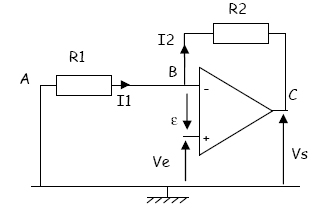
The configuration shown here is almost the same as the inverting configuration: only the input voltage Ve is applied directly to the positive input, and the point A is connected to the ground .

Also in this configuration, the feedback is negative. The linear functioning is hence possible.

In order to calculate the amplification Vs/Ve we use again the ideal op-amp model.

Hence we have :
V+ = V-
I1 = I2 since I- = 0

We can then write :

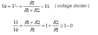
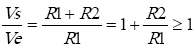
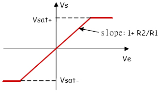
Vs and Ve have the same sign, the op-amp configuration is “non inverting”.

This relationship Vs(Ve) is valid only as long as the Vs voltage has not reached its saturation values.

The Vs(Ve) characteristic is hence as follows :

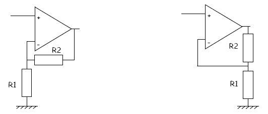
Other representations of the non-inverting op-amp configurations better show the voltage divider between the output and the negative input :


Characteristics of the non-inverting configuration  

Vs and Ve have the same sign
The Vs amplitude cannot be less than Ve
Input resistance : Re = Ve/ I1 =
Output resistance : Rs = 0
Page d'accueilTable des matièresNiveau supérieurPage précédenteHaut de la pagePage suivante