As its name suggests, this circuit is use to subtract the voltages applied to its 2 respective inputs. It allows also to adjust the amplification for each voltage.
1. Can this circuit have a linear functioning ?
Is it an inverting, configuration non-inverting configuration, neither ?
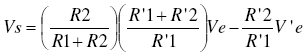
2. Use the model of the ideal op-amp and the circuit laws to show that :
3. What is the obtained function if all the resistors have the same value ?
Justify the name “subtractor” given to the circuit
4. Ve is the voltage delivered by a sensor. It can vary between -3V and +3V.
We want to change this range to: 0-5V, in order to connect an analog-digital converter.
If we choose R’2 = R’1, show that we need to choose the resistor values such that R2/R1 = 5/7
What kind and amplitude of voltage should we apply to V’e ?
5. Verify your results in the virtual lab, by simulating the voltage variation of the sensor when applying a triangular input voltage (range = +3 V, - 3V).